The structure under test varies from case to case. And this would require different size of hammers. The vendors of testing equipment typically supply the mini hammer for the PCB board testing, to the large sledge hammer for huge rotor testing from power plant.
The Hammer tip or its material plays a big role considering the upper frequency the test will need. The software tip hammer will result in relatively lower level impact with wider width of time. From the frequency domain, the auto power spectrum of the impact pulse will decay sooner than that from the harder hammer tip on. The following graph illustrates this in time domain and frequency domain. The rule is to pick the hammer tip material that its auto spectrum decays less than 6 dB to the upper frequency of the setup.
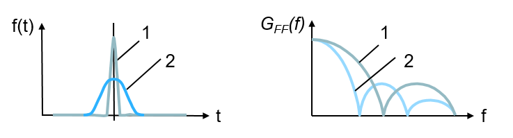
Soft (2) vs hard (1) tip of the hammer
To alleviate the leakage, Force/Exponential window shown as following can be applied.

Force/Exponential window with setup hammers
With the application of this window, the response channel data can be decaying to zero as shown in following graphs.
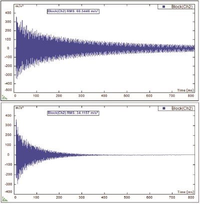
Response signal after Force/Exponential window
Though the Force/Exponential window helps to deal with the leakage issue, but it introduces extra damping to the result. Technically, the extra damping introduced can be extracted after the modal results are identified. If it is possible, increase the block size first to allow more measurement time so that the responses from the structure under test can decay to close to zero level. If this is the case, then no Force/Exponential window will be applied.
Double hit is a very common phenomenon during hammer impact testing. It tends to happen more easily when the hammer is hitting at the edge of the structure. When it happens, the spectrum of the excitation will be distorted and thus causes the measured FRF signal distorted too. When this happens, the current set of data will be discarded. Many modal software is implemented with the double hit detection and auto reject feature. With it is turned on, the data can be rejected automatically when double hit is detected.
Driving point defines the measurement for which its response DOF is the same as the excitation DOF. It can be used to help select the fixed driving point DOF for roving response hammer test, or the fixed response point DOF for roving excitation hammer test. The process is to select several DOFs on the mesh of the structure under test. Then the test to measure FRF will be performed. By checking these FRF signals from the Driving point selection process, the driving point from which the FRF illustrate most of the resonance peaks, and the valley exists between any two of resonances can be chosen as the driving point. This is done with the hammer impact test, but the result can be applied for the modal shake test too. The selected DOF can be applied for the modal shaker test to attached the driving stinger from the modal shaker.